As explained in the previous post, we identified the following factors that can contribute to condensation on new windows:
1. Low thermal performance of windows
2. Window and wall insulation misalignment
3. Window attachment method
4. High interior Relative Humidity (RH)
5. Low Emissivity coating on the glass surface facing the inside of the building
6. Interior blinds
7. Insufficient exposure of windows to heat flow
This post will cover the first two factors.
1. Low Thermal Performance of Windows:
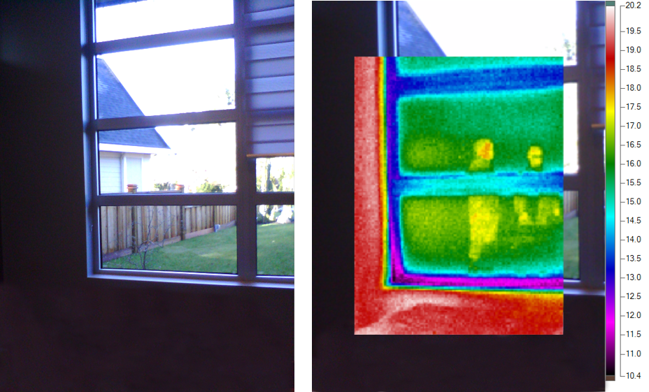
Windows with relatively low thermal performance can allow significant heat loss through them, leading in a temperature drop on the interior face of the windows. Such a temperature drop can pose the risk of condensation on the glazing section, at the perimeter of the glazing section, and on the frame. The risk of condensation is generally higher around the perimeter of the glazing section (due to additional heat loss through the glazing spacer) as well as on the frame. Also, the temperature of the bottom section of the window is generally lower than the upper sections due to the buoyancy effect (warm air rises and cold air sinks). These effects are shown below in the thermal imaging photos taken from the inside of a new, double-glazed thermally-broken aluminum frame window installed in 2014 in Vancouver. The colour pink represents areas with the highest rate of heat loss, and thus the lowest interior surface temperature.
Solutions:
For buildings in Canada, when operated under normal interior relative humidity levels, the risk of condensation is generally mitigated when windows are provided with:
- Insulated glazing units (IGUs), for example double glazed or triple glazed units. The space between the two panes of glass is filled with argon gas, and then a low emissivity coating is applied on one side of the glass facing the air space, and
- Warm-edge spacers, and
- Low conductivity frame material such as wood, fiberglass, or vinyl. In the case of an aluminum frame, the presence of an effective thermal break, and
- A heat source below the windows for double glazed assemblies (more on that to follow on the upcoming blogs).
2. Window & Wall Insulation Misalignment
The location of windows in relation to the plane of thermal insulation of a wall can play an important role in the overall performance of these assemblies with respect to the risk of condensation. Misalignment between the plane of thermal insulation of a window (generally assumed to be the center of an IGU) and the plane of the insulation of a wall, can result in additional heat loss at the transition between the two assemblies. In most cases, this will result in a drop in the temperature at the inside surface of the window along the transition. Such a temperature reduction can promote the risk of condensation under the right conditions.
To demonstrate the effect of the position of the window within the wall assembly and its effect on the condensation resistance, two-dimensional heat flow analysis was undertaken using THERM 7.4. Interior and exterior temperatures of 21 ˚C and -18 ˚C, respectively, were selected. The variation in the temperature of the interior face of a window (window frame and the edge of IGU) is shown in the below scenarios A, B, C, & D in which the location of a double-glazed thermally-broken aluminum window varies in relation to an interior-insulated 2” x 6” stud wall. It must emphasised that the intent of this analysis is to explore the performance of the scenarios in relation to one another.
In Scenario A, the window is installed flush with the exterior stucco cladding. It can be seen in the coloured infrared results that the interior temperature along the edge of the frame and the edge of IGU is very low. Such excess drop in temperature has to do with the following:
- Misalignment between the IGU and the wall insulation.
- By keeping the window flush with the cladding, the thermal break of the window is now located on the outside, rendering it ineffective.
- Locating the windows towards the outer plane of the wall, has also made it harder for the interior heat to reach the wall to window transition via convection and radiation, thus exacerbating the interior temperature drop of the windows along the wall to window transition.

Scenario A: Aluminum window flush with the stucco cladding. Window Jamb

Scenario A: Due to aesthetic reasons, the aluminum windows are pushed outward to make it flush with the stucco cladding. In doing so, the thermal break is now located on the outside, rendering it ineffective.
As can be seen in the coloured infrared results of Scenario B, moving the window slightly inward (this time flush with the wall plywood) leads to an increase in the temperature of the window along the frame and edge of IGU. This is because such configuration results in reduced rate of heat loss at the window to wall transition. This increased temperature corresponds directly to an increase in the condensation resistance of the window assembly compared Scenario A.
Scenario B: Aluminum window shifted slightly inward flush with the plywood. Window Jamb
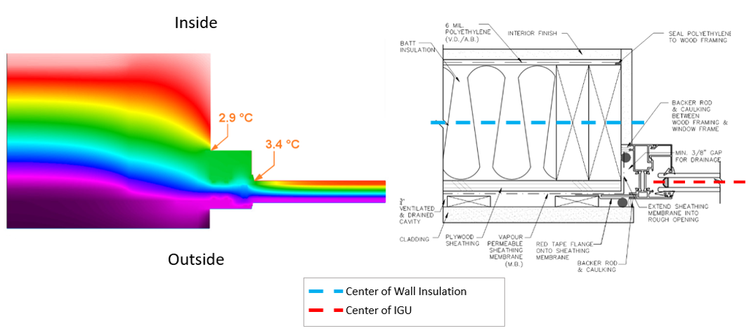
Even further heat loss reduction and subsequent temperature increase of the frame and the edge of the IGU can be achieved by moving the window further inward as is shown in Scenario C. This scenario achieves exact alignment between the center of IGU and the center of the wall insulation. The alignment of the insulation planes minimizes the path of heat loss along the window to wall transition and results in improved condensation resistance over Scenario B.
Scenario C: Window moved even further inward to align the center of the IGU with the center of the wall insulation. Window Jamb
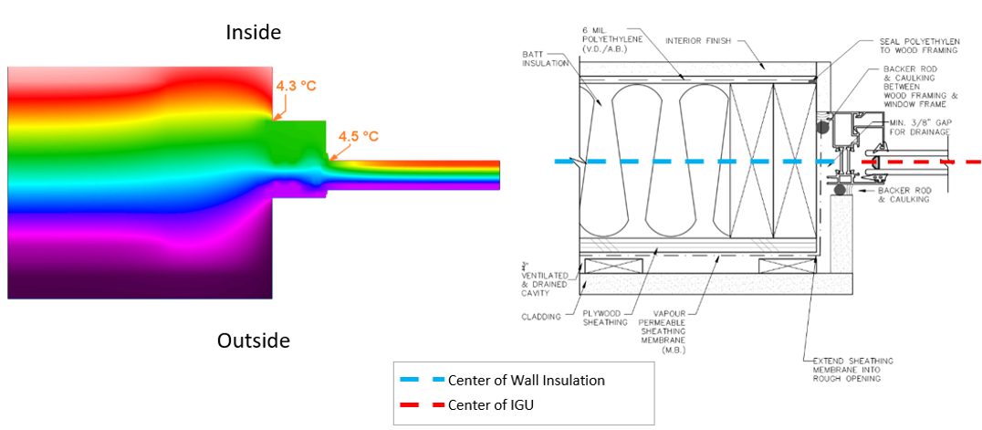
One may ask what would happen if the aluminum window is moved further inward, making it flush with the inside of the wall? Scenario D represents this condition. By moving the window even further inside, we are reintroducing the misalignment of the wall insulation and the IGU. So, logically, based on previous discussions, one would anticipate that this will result in lower overall condensation performance. Interestingly, this proves not to be the case.
Locating the window relatively flush with the inner plane of the wall, results in an increased rate of heat loss along the window to wall transition compared to Scenario C. This of course was predictable given the misalignment between the center of the IGU and the center of the wall insulation. That said, we see that the temperature of the interior window frame and edge of IGU is actually higher than Scenario C. This translates to improved condensation resistance of Scenario D over Scenario C.
Scenario D: Window moved inward to be flush with the interior. Window Jamb
The reason behind this irony is that by keeping the window as close as possible toward the inner plane of the wall, the interior heat has an easier time reaching the window to wall transition via radiation and convection, raising the temperature of these surfaces. In contrast, when window is located deep inside the wall (towards the exterior), some of the radiation heat exchange between inside of the room and the window/wall transition is blocked. Furthermore, convection heat transfer between the interior air and the window/wall transition is also not occurring effectively. These effects are further elaborated in the below figures.
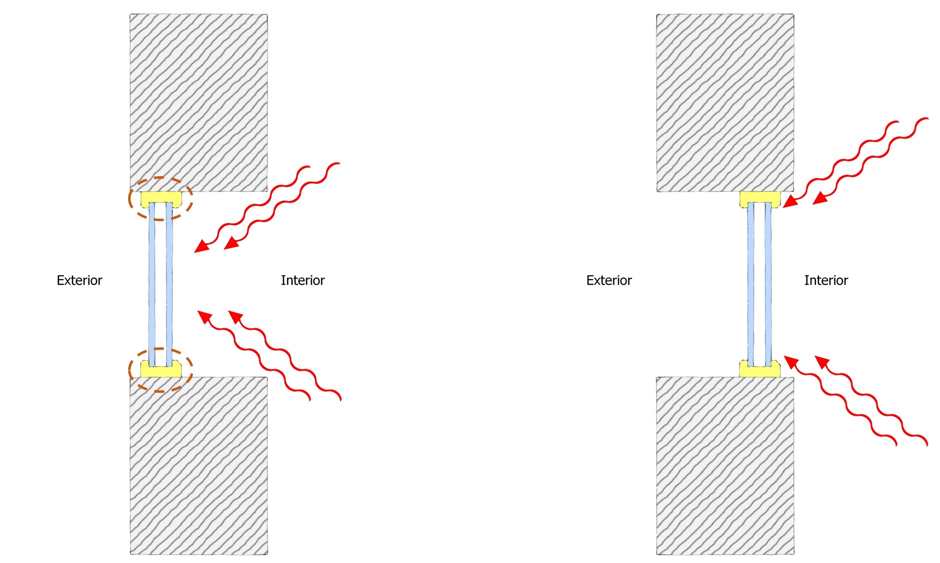
As seen on the left figure some of the interior net radiation heat exchange does not reach the perimeter of the window (shown with circles) since the radiation is intercepted by the recessed sections of the wall, thus reducing the condensation resistance of the window compared to the right figure
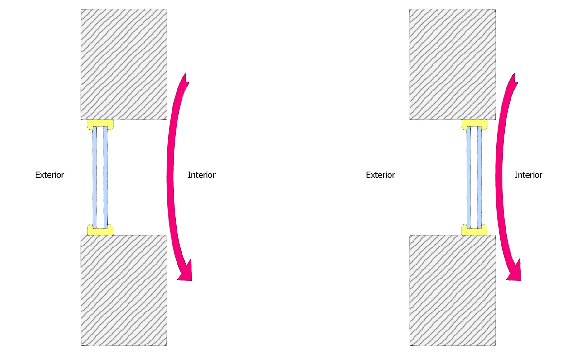
As seen on the left figure convection heat transfer between the interior air and the perimeter of the window is not occurring effectively, thus reducing the condensation resistance of the window compared to the right figure.
So in summary, the results of the above four explored scenarios suggest that:
- Scenario D results in the highest condensation resistance. This is due to the window being as close as possible toward the inner plane of the wall.
- Scenario C results in the lowest heat loss along the window to wall transition. This is due to the alignment between the center of the IGU and the center of the wall insulation.
As can be seen from the above scenarios, improving the condensation resistance of the window to wall transition and the reduction of heat loss at this transition may not necessarily go hand in hand. Therefore, when it comes to the placement of the window inside the wall assembly, it is important to choose a configuration that results in an optimum balance of not only improving the condensation resistance, but also reducing heat loss to increase energy efficiency. Based on the explored examples, it is our opinion that Scenario C would provide such an optimum balance.
The results of scenarios A, B, C and D are related to interior insulated wall where all the insulation is located inside the wall cavity. The principles explored here can be used as a foundation for the optimum design of window to wall transitions. However, it is important to note that when it comes to various wall assemblies (interior insulated, exterior insulated, split insulated) and window assemblies (window, curtain wall, window wall, etc.), specific analysis should to be implemented to find out the optimum location of the window inside the wall that would result in an optimum balance between the reduction of the heat loss as well as improving the condensation resistance of the window to wall transition.
Solutions
- During the design stage, pay specific attention to the location of the window in relation to the wall insulation for interior insulated wall, spilt insulated wall, and exterior insulated wall. This is specifically important when it comes to projects involving replacement of the existing windows.
- Aim for optimum balance between the reduction of heat loss at the wall to window transition (ie: energy efficiency) and improving the condensation resistance of window. As mentioned earlier, achieving alignment between the centre of the IGU and the centre of the wall insulation results in the lowest heat flow along the window to wall transition, while locating the window closer to the inside of the house generally results in improving the condensation resistance of the window.
- If, during the tender stage, a different window assembly is proposed, ensure the two steps above are revisited.
- At the shop drawing review stage, ensure the proposed design by the window manufacturer meets the design intent with regard to the requirements mentioned above.
- During construction, implement quality assurance measures to maintain the intended requirements.