As you recall from our discussions so far, the following factors can contribute to condensation on new windows:
1. Low thermal performance of windows
2. Window and wall insulation misalignment
3. Window attachment method
4. High interior Relative Humidity (RH)
5. Low Emissivity coating on the glass surface facing the inside of the building
6. Interior blinds
7. Insufficient exposure of windows to heat flow.
The first two factors were covered in the previous post. This post will explore the third factor: Window attached method
3. Window Attachment
Some attachment methods of windows inside the wall rough opening can pose the risk of compromising the condensation resistance of the windows. One example of such methods is shown in the below photo pertaining to a double-glazed thermally-broken aluminum window installed in 2014 in a low rise residential building in Vancouver. In this case, continuous aluminum angles were added all around the windows to serve as the fastening mechanism of windows to rough openings. As you will see in the upcoming discussion, the aluminum angles have compromised the condensation resistance of the windows, and have served as one of the contributing factors to occurrence of condensation. This does not have to do with the aluminum angles itself, but rather the location of the angles in relation to the thermal break of the aluminum frame.
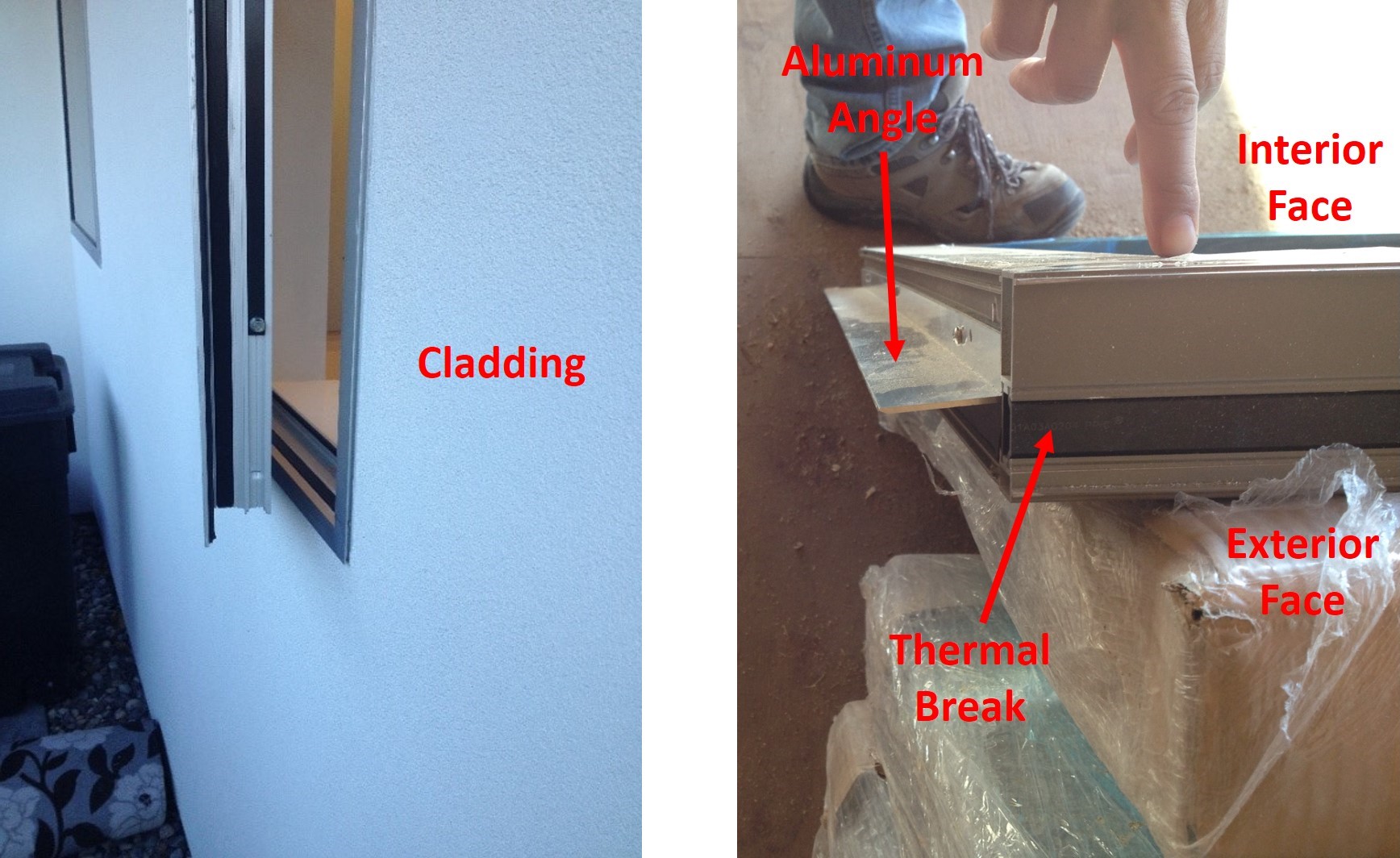

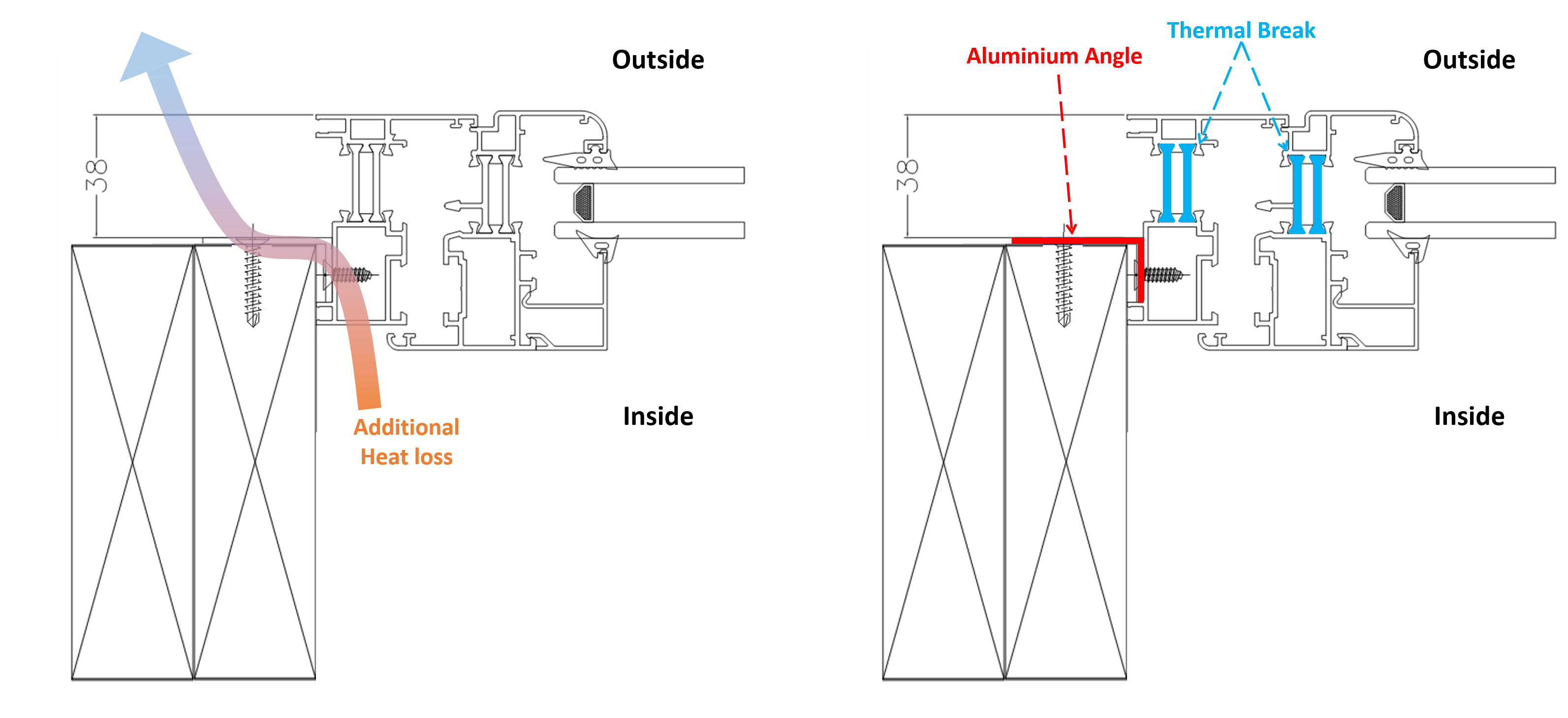
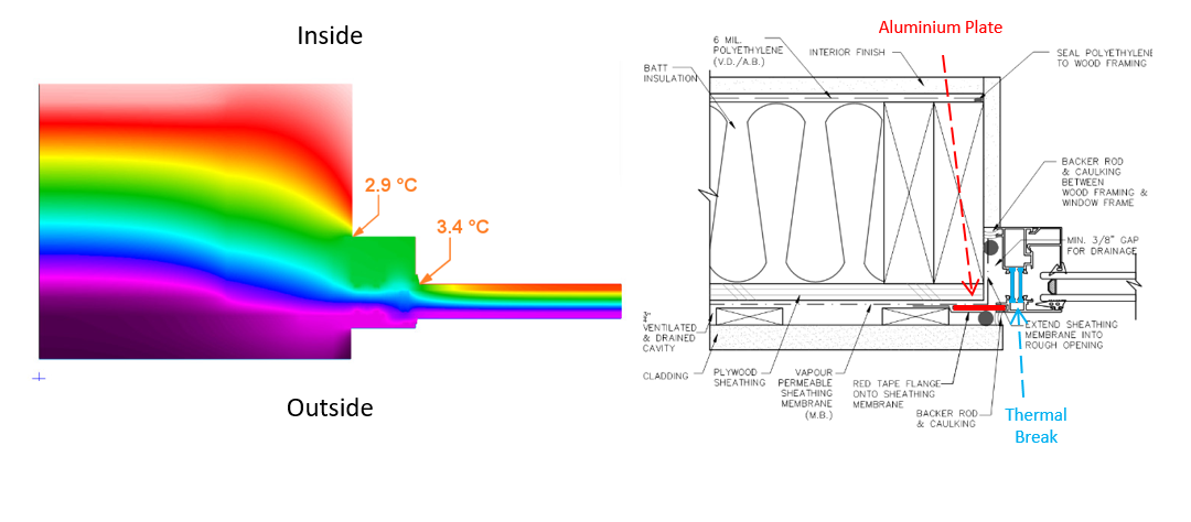
The building in question had an aesthetics requirement of keeping the exterior of the windows flush with the exterior of the wall cladding, in this case stucco. To achieve this intent, during the construction, the aluminum angles were fastened as close as possible towards the inside of the windows, so that the windows were pushed as far out as possible inside the rough opening. In doing so, the aluminum angles ended up inboard of the frame thermal break and as such, the thermal break of the aluminum frame is bypassed by the angles, creating a thermal bridge. This has resulted in additional heat loss, and the consequent reduction in the interior surface temperature of the windows near the flange, thus reducing the condensation resistance of the window. These effects are shown below.
To get a better understanding of the effect of the aluminum angle and its location on the condensation resistance of the window, two-dimensional heat flow analysis was undertaken using THERM 7.4. Interior and exterior temperatures of 21 ˚C and -18 ˚C, respectively, were selected. Three scenarios A, B, and C, focussing on the window jamb to wall transition, were evaluated.
In Scenario A, the aluminum angle is located inboard of the window thermal break (similar to what was explained earlier) with the intent to push the window outward, making it flush with the stucco cladding. As can been in the colour infrared results, this configuration results in a substantial drop in the temperature of the window frame and the edge of the Insulated Glazing Unit (IGU). As discussed earlier, this has to do with the thermal break being bypassed by the angles. In addition, the window is located too far out in the rough opening, thereby reducing its exposure to interior heat. This latter effect was discussed in detail in Part 2.
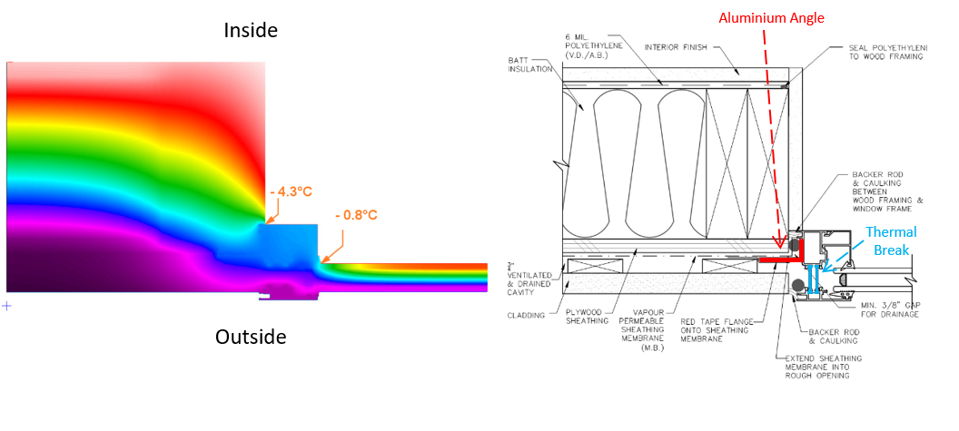
Scenario A: Aluminum flange is located inboard of the thermal break. Window Jamb
In Scenario B, the aluminum window is located at the same location as that of Scenario A. However, the aluminum angles are now eliminated. The intent is to see how much of a difference the absence of the angle can have on the condensation performance of the window. As shown in the colour infrared results below, by eliminating the angles, there is an increase in the temperature of the window frame and the edge of IGU, thus increasing the overall condensation resistance of the window.
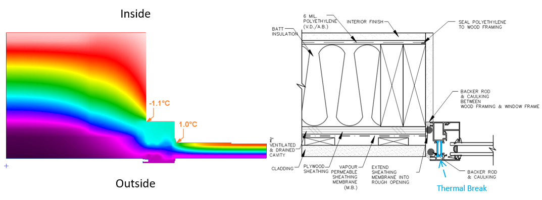
Scenario B: Aluminum flange is eliminated to explore the effect on the condensation resistance. Window Jamb
In Scenario C, the aluminum window is now moved inward by approximately 1 ½”, in order to somewhat increase the exposure of the window to interior heat, without overly compromising the aesthetic requirements. In addition, a continuous aluminum plate is now used all around the window to secure the window in the rough opening (given the profile of the window, an aluminum plate is used rather than an aluminum angle). This plate is located outboard of the window thermal break. As shown in the colour infrared results, these modifications have resulted in a noticeable increase in the temperature of the window frame and the edge of the IGU, translating to increased condensation resistance of the window.
Scenario C: Window is moved towards the inside slightly. Also an aluminum plate is located outboard of the thermal break for the attachment of the window to the rough opening. Window Jamb
The above discussion illustrated the impact of the attachment method of a window (in this case a thermally broken aluminum window) on the overall condensation performance of the window. The discussion emphasised that the window attachment method requires specific attention in order to ensure that the overall condensation performance of the window is not negatively affected.
In addition to the attachment method, the detailing of the window rough opening can also have an impact on the overall condensation performance of the window. One such example which will be explored below is the back dam at the window sill.
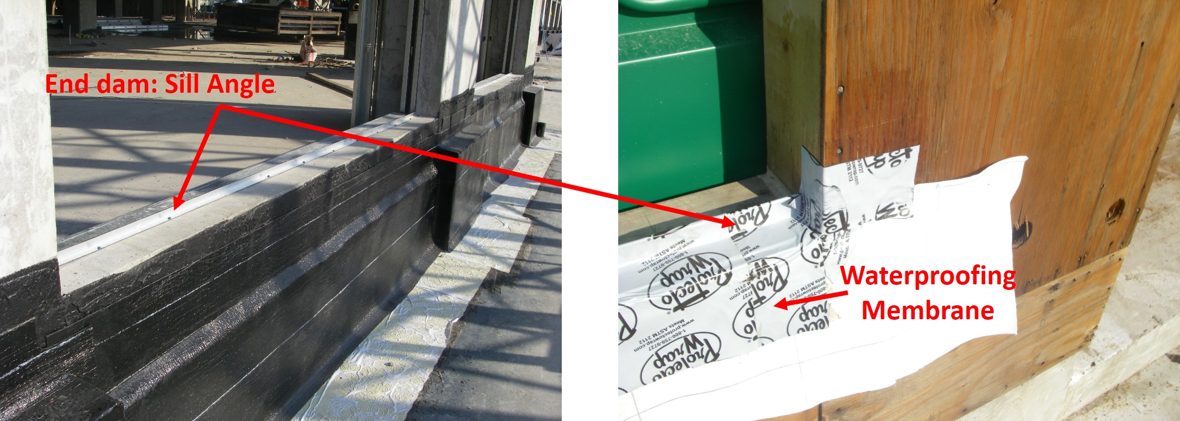
When it comes to improving the rain penetration control at the window/wall transition, installing a back dam at the window sill has been a typical practice in the lower mainland of British Columbia, Canada. The height difference created by the back dam adds a level of protection in reducing the risk of water ingress. The back dam can be formed by several methods. One common method utilizes an aluminum or steel angle along the window sill as shown in the below photos. A layer of waterproofing membrane is then installed along the window sill, and up and over the angle.
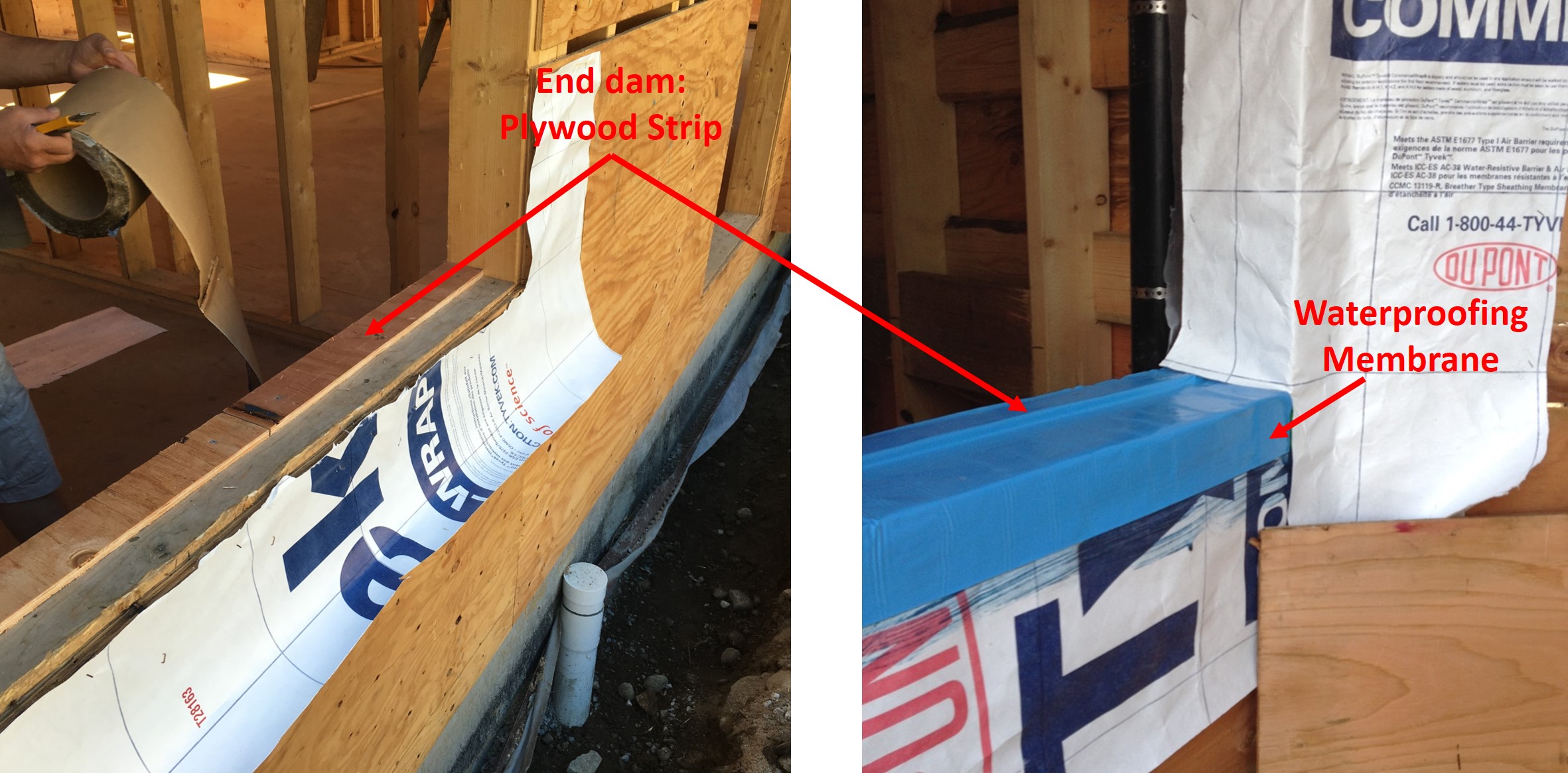
In another method, a plywood strip is installed along the sill to serve as the back dam. Again, a waterproofing membrane is installed along the sill, and extended and up and over the plywood strip as shown in the below photo.
Although these two methods serve the same purpose, they can have different impacts on the condensation performance of the window along the sill. These impacts are explored in Scenarios D, E, and F using a vinyl window. In Scenario D, an aluminum angle is installed along the sill with the horizontal leg of the angle facing the outside. Scenario E is the same as Scenario D; however, the horizontal leg of the angle is now facing towards the inside of the building. In Scenario F, the aluminum angle is replaced with a plywood strip. The results of the two-dimensional heat flow analysis using THERM 7.4. are shown below, using interior and exterior temperatures of 21 ˚C and -18 ˚C, respectively.
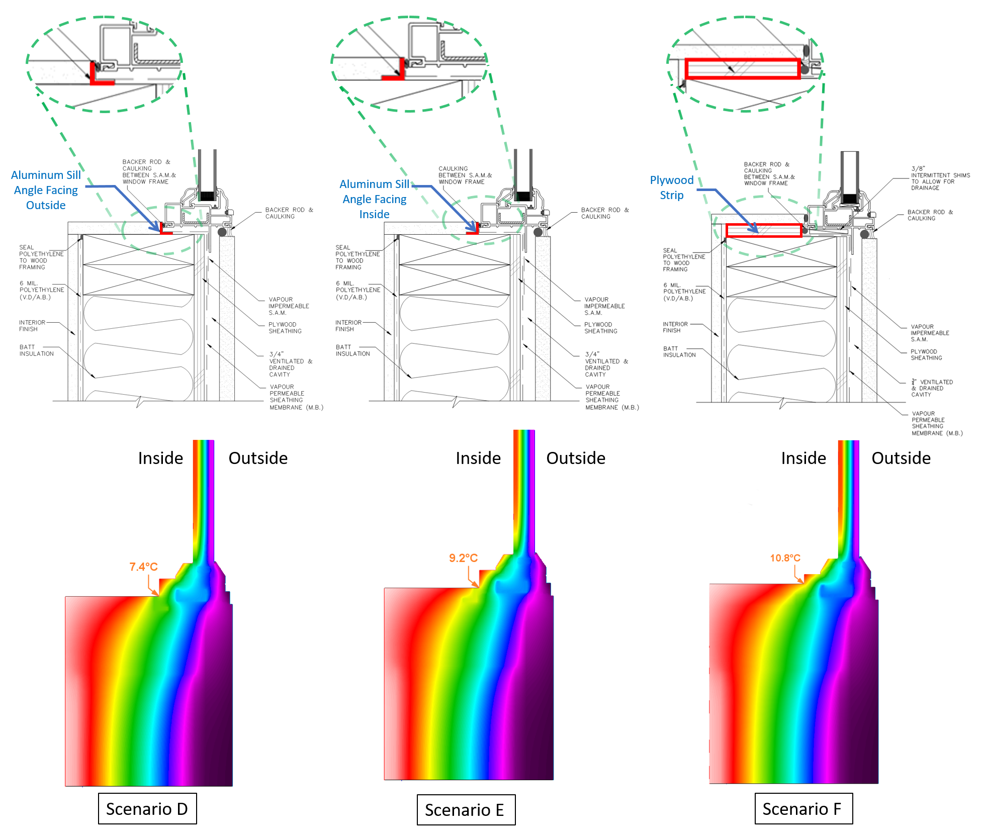
As can be seen, Scenario E with the plywood back dam, offers the highest condensation resistance among the three evaluated Scenarios. This should not come as a surprise given that wood has much lower heat conductivity than aluminum, translating to a reduced rate of heat loss. When comparing Scenarios D and F, Scenario F (in which the horizontal leg of the angle is facing towards the inside of the building) offers improved condensation resistance. Again, this result is intuitively expected given that a larger area of the angle is exposed to the warm interior air in Scenario F.
Above results suggest that when it comes to selecting a material for the back dam, the logical choice is a material that has the lowest heat conductivity. To that note, the use of aluminum or steel angles should be avoided for this application. That said, it is acknowledged that sometimes, the structural attachment of the window to the rough opening demands the need for having a steel or aluminum angle along the sill. When dealing with these situations, one can still explore potential solutions that would render the impact of the steel/aluminum angles on the condensation and thermal performance of the windows.